
After the repeatedly tested and repeated discusses modification, the Latest LCD Screen Constant Current/Voltage Power Module have already come to meet with you.
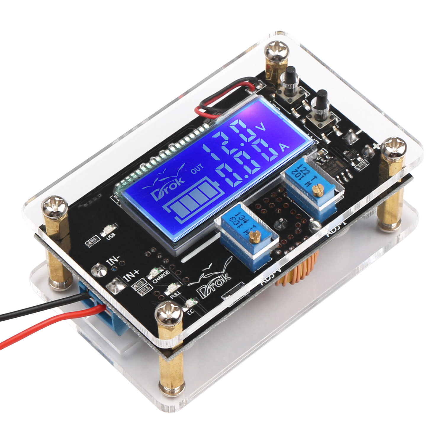
With voltage and current LCD digital display, no need extra multimeter, convenient and powerful. The module is also equipped with crystal acrylic shell and USB interface, can satisfy your various application. However, we also received some questions from the reviewers and customers, so this is written for modifying the product description. For any further concerns, please write to us we will be more than happy to assist you.
How to Calibrate Accuracy?
Because of the wide voltage and current range of the module, there will be slight difference within certain range in measuring the electronic components. For this issue, this module is specially added the calibration function to completely solve the measurement error and make the measurement more accurate. If you found that the measured value is not accurate, you can calibrate the module by following methods. Just for the first time using a calibrated once.
Voltage calibration: in the state of power off, press “SET” button and do no release, power up the module then it will enter voltage calibration mode. The LCD screen will flash. At this time, release the “SET” button. “SET” button is for adding value, “ENT” button is for reducing value, adjust the input voltage to right value. E.g. : if the input voltage is 12.65V, adjust the voltage of the module to 12.65V, the value will be saved automatically in 2 seconds, switch off the power then the calibration is completed.
Current calibration: this function is suitable for the case that there is current displayed when without load or the displayed value is much larger. In the state of power off, press “ENT” button and do not release, power up the module, then it will enter current calibration mode. The LCD screen will flash. At this time, release “ENT” button, “SET” button is for adding value, “ENT” button is for reducing value, adjust the current to right value. E.g.: in state without load, if the current displays 0.02A, adjust the value to 0.00A, the value will be saved automatically in 2 seconds, switch off the power then the calibration is completed.
The Output Voltage is Unable to Adjust??
The default output voltage of the module is about 20V. If the voltage cannot be adjusted, please counter clockwise rotate the ADJ-V potentiometer for more than 10 laps until there is a change in the voltage value, then the voltage can be adjusted normally.
Operating Tips that Require Attention
The output voltage of USB interface is the same as the output voltage of the module. There is no output through the USB interface when the USB indicator is off. There is not fixed 5V output through the USB when the USB indicator is on. If you need to charge for your USB device, please set the output to 5V before charging. If the output voltage is higher than 5.5V, the LCD screen will flash to remind you to adjust the voltage, otherwise, your USB device will be damaged. The USB output is off by default to ensure that your device is not damaged by misplugging.
Hi. There is a charge LED and battery charge display on the screen. Is there a charge function on the board?
Hello Mark,
This buck converter have a charge function.
Wide applications:used as an ordinary step-down modules with over-current protection capabilities, as a battery charger, as a constant current LED driver module.
Hope this can help you.
Best regards
Hi, I am trying to convert an Apple Aiport Express (Generation 2) to run on DC for use in-car.
I have tried a designated 5v – 3v 800ma step down buck and powered over USB, and a 4.5v – 12v to 3.3v step down buck and tried USB, ATX PSU 12v, and in-car 12v. Same problem…
The issue I have is no matter how well insulated the wires etc.. I get a loud, constant popping noise and distortion coming out of the speakers when powered over DC… this disappears when I re-instate the AC PSU.
I have tried 2 different Airport Expresses and various forms of wiring/grounding/connecting and the issue is persistent.
Would this device address the issues I am having seeing as it appears to be far more complex than the step down bucks I have been using?
This is a common modification and there are instructables, youtube videos etc.. showing successful with no issues – but I have followed all of these to the letter and cannot get rid of this problem
Hello AC,
Thank you for writing in.
The Apple Aiport Express is powered by AC, but this product is a DC to DC buck converter.
This product maybe not suitable for your application.
Best regards
Does anyone know a part number or where I can find a nice enclosure for the DROK LM2596 digital Control Voltage Regulator DC Buck Converter Power Supply?
Hello steve,
Thank you for writing in.
Here is a LM2596 board with nice enclosure:
Part number:#091029
DROK® LM2596 DC Buck Volt Regulator 36V to 24V 12V 5V 3.3V 3V Converters Constant Volt&Amp 5-36V to 1.25-32V 5A 75W Step-down LED Driver Switch Power Supply Digital LED Voltmeter USB Output
Hope this can help you.
Best regards
So can the output voltage be adjusted .1v increments?or whta increments can the output be adjusted? I want to go from either 12v or 20v in to 7.4-9.0v 3amp max in .1v increments. Which bucks with display do you offer to support this? And can I send 5.5v @ 2.4a through the USB out?
Hello Hoops,


Thank you for writing in.
Yes, the output of this product can be set to 7.4-9V.
You can set the value of the output as you need by the potentiometer.
There is a LCD monitor for you to check the output voltage and ampere.
The value of USB output is the same as the output of the terminals, so you can set the USB output as you need like setting the values of the terminal output.
Here are two images that we think is useful to you:
Hope this can help you.
Best regards
0.1 V increments, I believe
I would love to get one of these, but I can’t find a place that ships to nor sells in Canada
Hello Jon,
Thank you for your interest in our product.
You can purchase the product from us directly.
Could you please send us an email(service at droking dot com) to tell us the quantity you need?
Looking forward to hearing from you.
Best regards
Thanks for the reply, I have sent you a mail
Hello Jon,
Thank you for your reply.
We will check it and give you a reply as soon as possible.
Best regards
When i hook this bad boy up to a 24v solar panel (it’s really a 18v) before i connect my battery pack it reads 18 v input but when I connect a battery pack to the USB port (USB port set to 5v output) it reads 8v in and 5v out. Why does it report 8v input after i connect my battery pack?
Hello Gabe,
Thank you for writing in.
This problem maybe caused by the output current is too low which makes the output power is too low to drive the module.
Could you please try to use another power supply (e.g 18V battery) to test if the product can work or not?
If not, please feel free to write back to us.
Hope this can help you.
Best regards
How does the charging mode work in detail? Does the LCD display’s battery icon change to match charging level? Is there an online manual?
Hello Jsaon,
Thank you for writing in.
The LCD display’s battery icon cannot change when the battery level changes.
Use as a battery charger:
1. Ensure the floating charge voltage and charging current (e.g.the parameters of a lithium battery is 3.7V/2200mAh,then the floating charge voltage is 4.2V, the max. charging current is 1c,i.e. 2200mA)
2. Under no load condition, adjusting “ADJ-V” potentiometer to make the output voltage reach the floating charge voltage;
3. Shorting the output terminal of the module directly (use a thick lead wire or tweezers to short the output terminals, please note that do not adjust the voltage dring shorting). At this time, adjusting “ADJ-I”potentiometer to make the displayed current value reach the set charging current value or connect the load which also can adjust the current.
4. The value of the charging turn light is set to 0.1 times of charging current. During the charging process, the current of the battery will decrease generally, then constant current charging will be changed to constant voltage charging. For example, the charging current value is set to 1A. When the charging current is less than 0.1A, the yellow charging indicator will be off and the blue full-charged indicator will be on, which means the battery is full-charged. When the charging is completed, please cut off the battery firstly, then ct off the output terminals, which can avoid the backflow of the battery damaging the module.
Here is the instruction of the product, please check it:
Instruction_180080
Hope this can help you.
Best regards
Why do not I see the current in the dispaly even if imposed as 4v value? And because I can not adjust the current with the potentiometer ? I always value 0 or the value that I set in the calibration.
Hello Piero,
Thank you for writing in.
Have you connected a load when you adjust the current potentiometer?
If not, please try to connect a load to check if the current values 0 and the current potentiometer work or not.
Please note that the adjusting current in constant state, the real output current of the load should be higher than the set current, otherwise the module will become work in constant voltage state. Not adjusting the current to 2A, then all the connected devices will become 2A.
Hope this can help you.
Best regards
I hope I have ordered the right gadget! I’ve already ordered this awesome looking gadget but I’m questioning rather it’s the right one.
I have three ASUS MB169B+ that runs off of USB power of 5 volts and each one uses about 0.80 amps. My USB volt/amp meter says it pulling 2.2 amps during normal operation of all three monitors. I understand this can pull up to 5 amps @ 5 volts, right? If so, is that through the USB port or only through the blue connector?
I originally bought your DROK #090945 on Amazon and tried using it with my three monitors. It works great except that it gets a bit too hot for my comfort. I’m worried that it will fry itself over time which is why I turned around and bought this gadget on this page.
Would love to hear your thoughts on this and give me some recommendations. Am I going down the right path in buying this product for my needs or do you think the 2 Amp step-down converter is sufficient when it’s drawing ~1.75~ amps on a 2 Amp max DROK board? Thanks so much for your products and your expertise in this!
Hello Buddy Steve,
Thank you for writing in.
Please note that the output voltage of the USB interface is not fixed 5V.
The output voltage of the blue terminals and the one of the USB interface are the same.
And the output current is depended on the need of the load.
The output current of this product is Max.5V, adjustable, recommend the use of within 4.5A. (Over 2A or 35W, please enhance heat dissipation.)
Hope this can help you.
Best regards
Do you sell the heat dissipation that will fit this product? If not, then what size do I need?
I see this device doesn’t have input polarity protection. Can you please advise if this is the case and how I can I implement this piece via diode or mosfet
Hello Savio,
Thank you for writing in.
For the input polarity protection, you can add a diode in the positive side of the input.
Hope this can help you.
Best regards
So to be clear. The battery icon on the LCD will always display Full as it is just an image to display that this board can also charge batteries. Is this correct?
Hello kicker22004,
Thank you for writing in.
The battery icon on the LCD is just an image, cannot reflect the charging status of the battery.
Hope this can help you.
Best regards
Ok thank you for that, DO you guys offer replacement housing for this device? I modified mine to provide me with a barrel plug for input and broke part of my housing by mistake. Thank you
Links to what I’ve changed. I made the mistake of going to fast on my drill is all.
https://goo.gl/photos/SQS3sHs9RWsL48y48
https://goo.gl/photos/VeSboHHDM77HpGQz5
Hello kicker22004,
Thank you for writing in.
So sorry that we do not have the case sold separately.
Beg your understanding.
Best regards
Not a problem, I love this little board so far and will probably order another one and make a housing for this one in my project.
Hello kicker22004,
Thank you for your understanding.
We are so glad that the product can meet your need.
If there is any question, please feel free to contact us.
Best regards
Hi, can the device be set to remember it should output via USB? Every time the power is switched off / on I have to manually set the device to output via USB.
Hello Andy,
Thank you for writing in.
Could you please tell us which item you mention?
We are not sure which product you mention.
Hope you can understand.
Best regards
Hello,
Can the USB port be switched on by default when switched on?
thank you
Hello Heiko,
Thank you for writing in.
We are sorry that it don’t have USB port.
If there is any question, please feel free to contact us.
Best regards.
Hello, i purchased this from Amazon Canada and received it on time. HOwever, the case seems maybe not to be the right part. The shell pieces seem to fit, but on the back side, there is a cut-out in the cover for what looks like a possible fan. So did i receive the right shell with this product? Or is there a way or need to add a small fan to this unit? Thanks.
Hello Tom,
Thank you for writing in.
Could you please send us the link of product you bought so that we can confirm the item?
And please take some picture about the item for let us check it.
Please don’t worry, we will find solution for you.
Best regards.
I am having issues trying to get my volts adjusted. I have it hooked up to 13.9v and am trying to stay at 12v. Turned adj-v counter clockwise but have had no results getting voltage to adjust.
Hello Witt,
Thanks for writing in.
To find out solution for you, could you please send us the link of product or your order ID so that we can confirm the item?
And please tell us more details about other parameters, such as the load you connect.
Look forward to your reply.
Best regards
can this step up voltage such as 5 volts to an even 14 volts for battery charging?
Hello dean,
Thank you for writing in.
Is the following item that you mention?
https://www.amazon.com/dp/B01FQH4M82
We are sorry this is buck module, which can only step down voltage.
For more questions, please feel free to contact us.
Best regards.
Good Morning, Why do not I see the current in the dispaly when USB load is connected? And because I can not adjust the current with the potentiometer ? I always value 0 or the value that I set in the calibration.
The USB output is activated and the load (power bank) is charging.
Hello Franco,
Thank you for writing in.
To find out solution for you, would you please tell us more details about the problem?
Do you mean the current display is 0? What happened if there is no USB output?
If you can, we sincerely hope you can take a short video to let us check the problem.
That will be a great help. You can send the video to our service#droking dot com ( please replace # with @).
Look forward to your reply.
Best regards.
Hi ! If y would like a 19V output voltage, I must have 20.5V input minimum ?
I’m right ?
Hello Higgins,
Thank you for writing in.
Do you mention this item?
180080
Input for this item must be be 1.5 higher than output,so your thinking is right.
For more question, please let us know.
Best regards.
Yes it is, many thxs
My need it to supply PCs in a car with a 12V auxiliary battery.
I think I will put first your 12DC to 24DC booster 3A/72W in input of the DC-DC Adjustable Buck Voltage Converter 5A to can adjust following values output:
– 19V 2,37A (45W)
– 16,5V 3,65A (60W)
– 9V 0,2A (2W)
Please let me know if it’s works and if I have to order an heatsink
Hello Higgins,
We can’t sure this product “12DC to 24DC booster 3A/72W”.
According to your description, is the input voltage for #180080 DC24V?
When the output power is over 35W or the output current is over 3A , heat sink is necessary.
We suggest it has better not over 50W.
For more question, please let us know.
Best regards,
DROK
Anybody please ?
Problematic deriving the high currents needed for the 3.3V rails!
The 12V rail should be ok to run at battery voltage (11.5 – 13.5 V). Even while charging the battery at 14.5 V SHOULD be ok.
I’m currently designing a motorcycle Bluetooth ignition system using an arduino and the onboard regulator is over heating.
I plan to use one of your regulators to supply a steady 9v to the arduino to negate this issue bit I’m curious how much power the LCD screen draws since it will be running off a motorcycle battery and every mW saved prolongs the battery stand by level
Hello Soul,
Thank you for writing in.
Would you please tell us which product you are talking about?
Best regards.
Supply it with 7V with a SWITCHING or buck regulator OR 5V directly to the 5V rail (3V3) for a 3.3V Arduino.