
Check at
Amazon.com: https://www.amazon.com/dp/B01FNVESV2
Amazon.co.uk: https://www.amazon.co.uk/dp/B01FNXA1UC
Amazon.de: https://www.amazon.de/dp/B01FNYXL1C
Amazon.it: https://www.amazon.it/dp/B01FNZPBQO
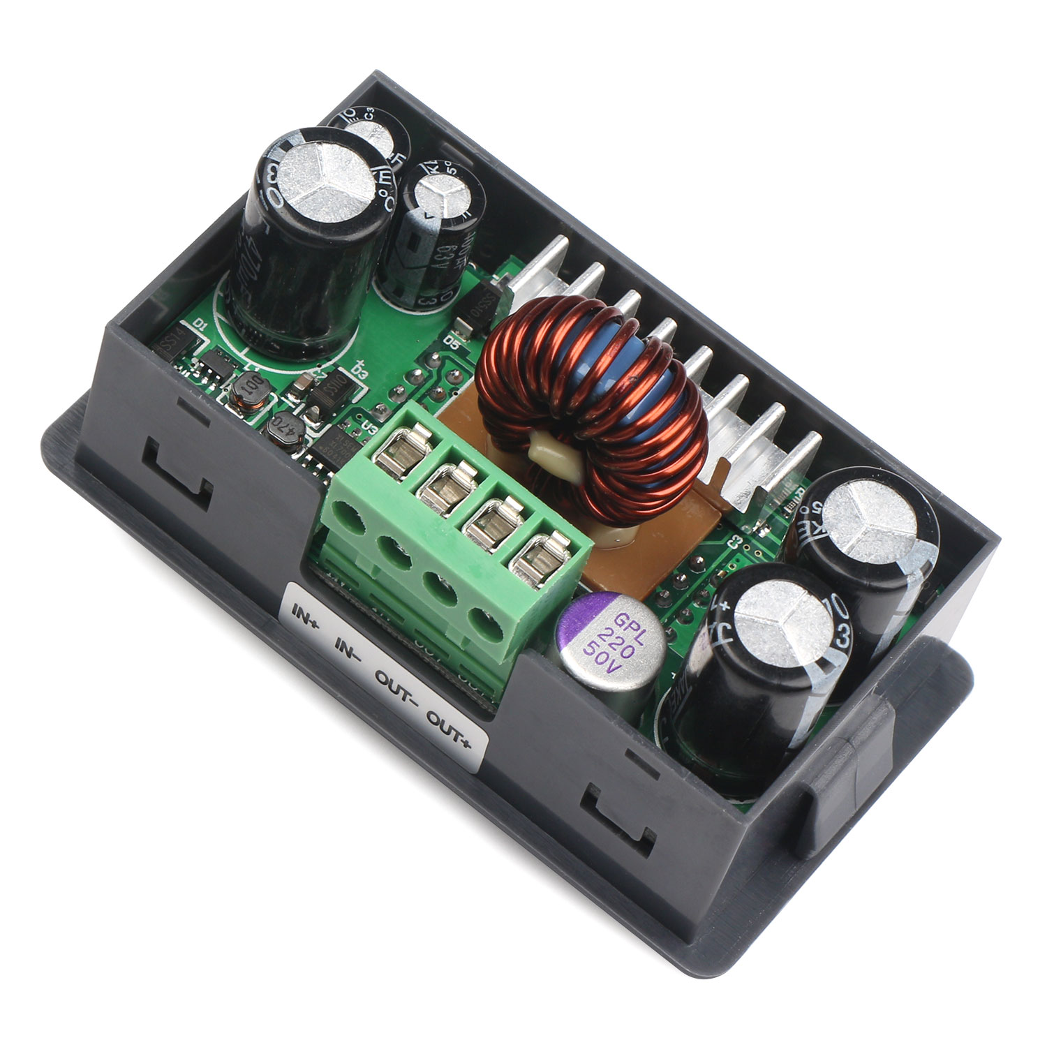
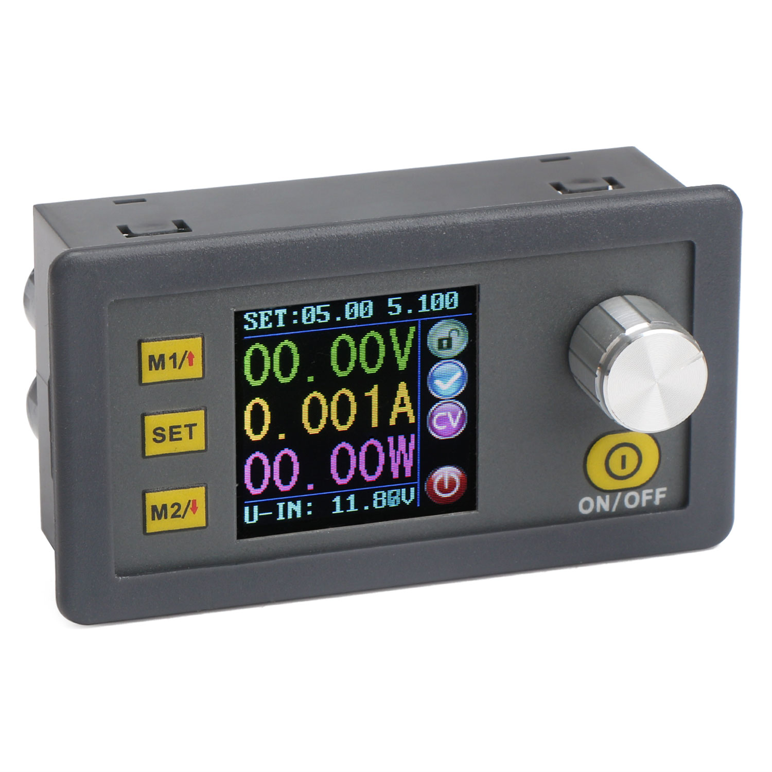 DP50V5A DC numerical control regulated power supply is an adjustable step down module that integrates analog integration and numerical control. This module adopts STM32 single-chip microcomputer and the synchronous rectification IC as main control chip, which ensure the high efficiency of the module and raise/reduce the voltage instantaneously in case of no load. Using MOS anti-reversed connection protection circuit in the input not only protects the product but also effectively reduce the power consumption. What’s more, in order to reduce the output ripple and the interference to the power supply, the module adopts a 63V100UF solid capacitor and a 63V/470UF filter capacitor parallel connected in the input. In the output, it adopts a 50V/220UF solid capacitor and two 63V/470UF filter capacitors.
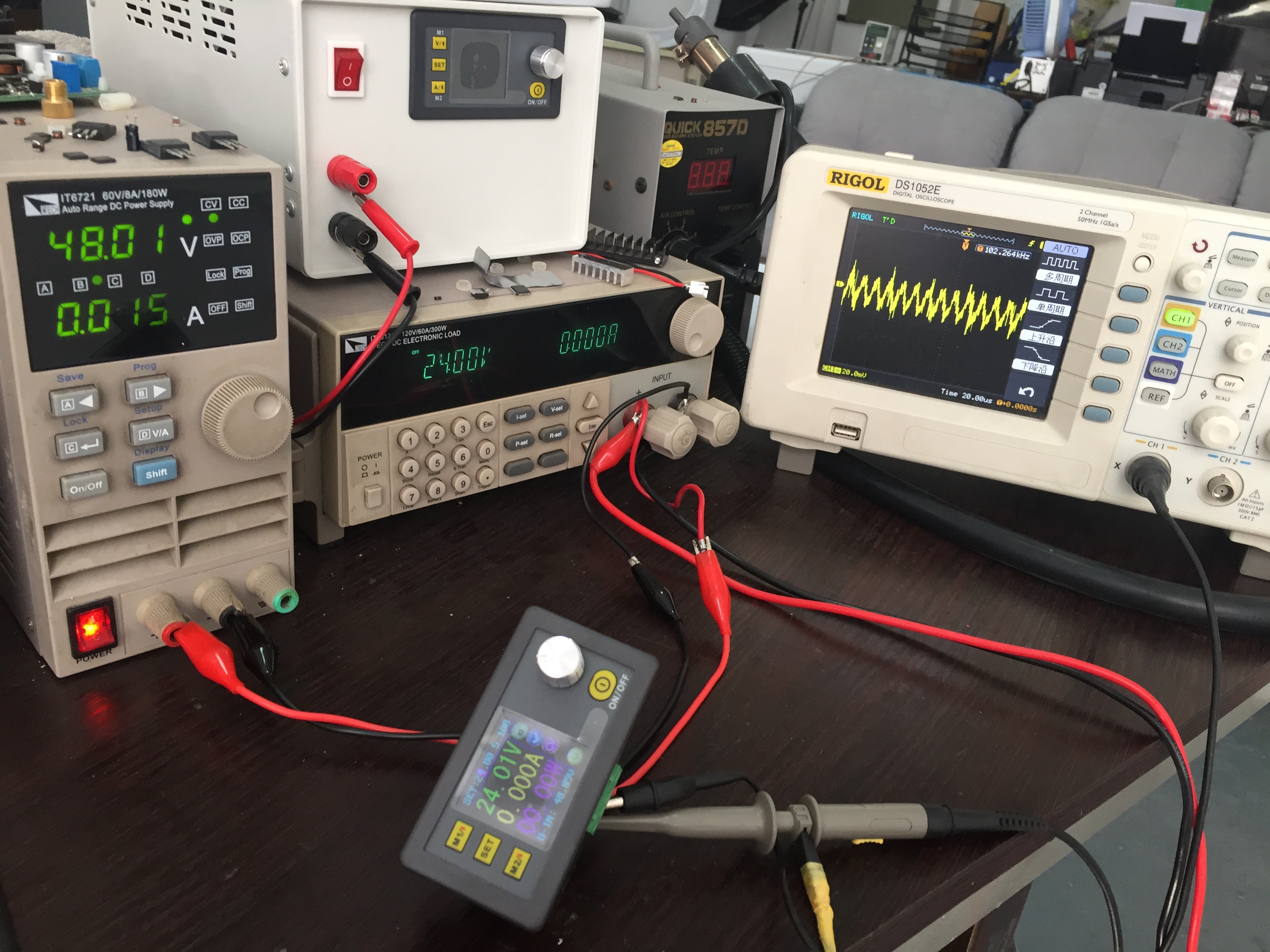
Facts speak louder than the words. The following is the test result of the output ripper and the accuracy , which is tested by professional equipment.
Firstly, we adjust the output voltage to 24V, then use oscilloscope to test the output ripper when the output is 24V0A. From the image, there is no high fluctuation.
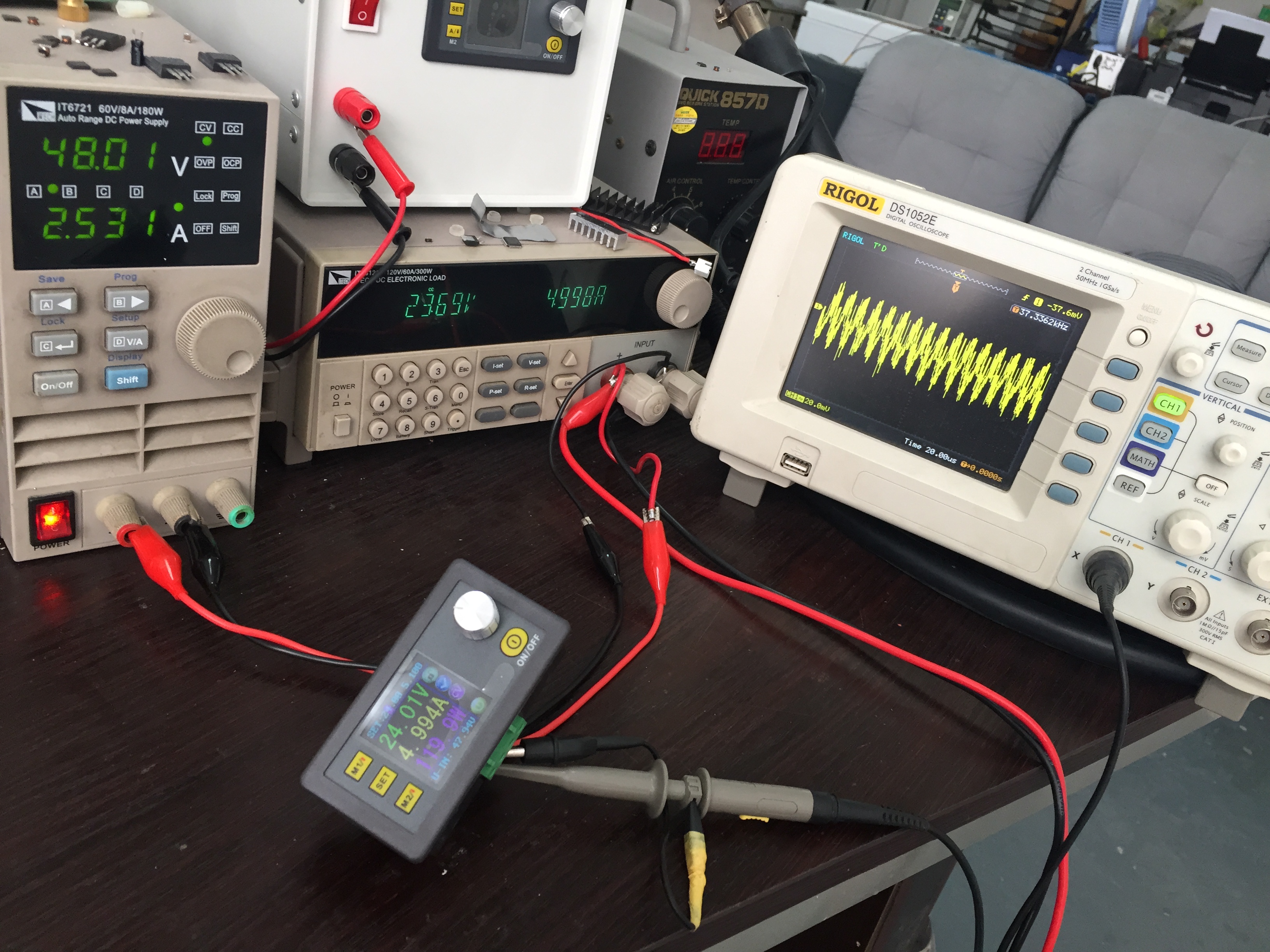
When the output current is adjusted to 5A, the ripper become more intensive but no high fluctuation.
According to this testing result, the output ripper of the module is very low.
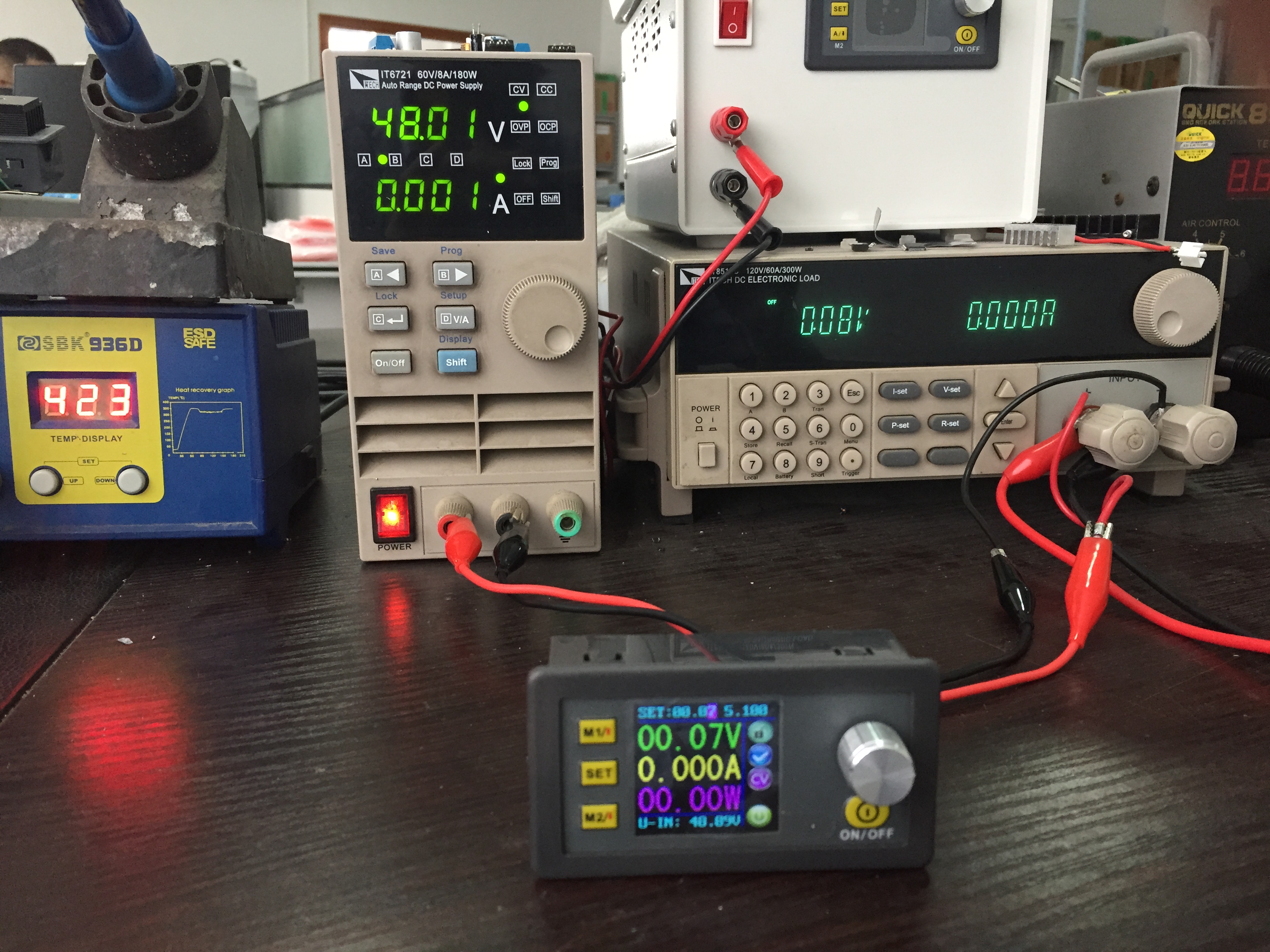
Here is the testing of the accuracy of the output voltage.
Firstly, adjust the output voltage to 0.07V, then we can see that the DC electronic load display 0.08V, which the error is small.
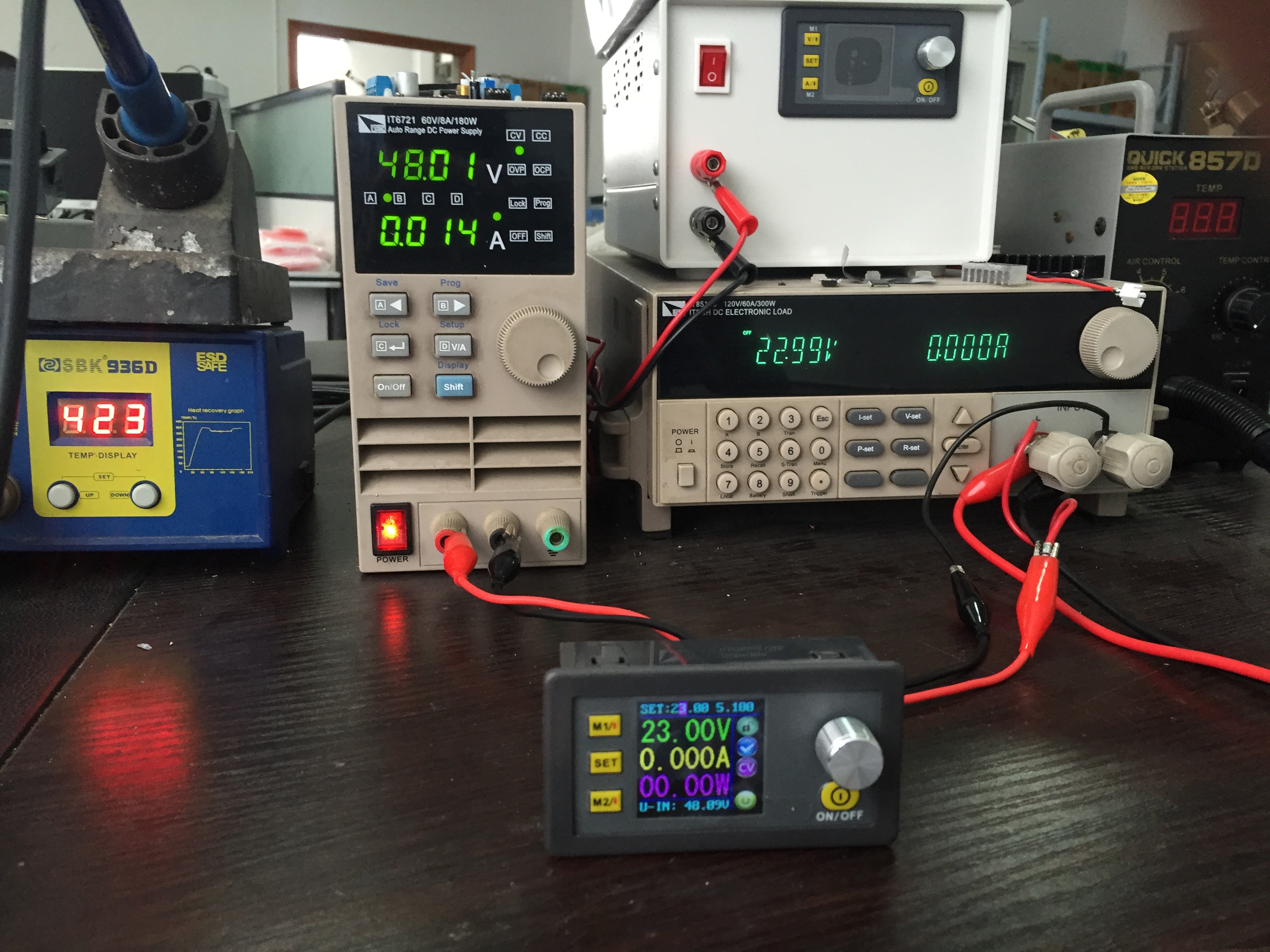
When the output voltage is adjusted to 23V:
The last but not the least, the following is the using experience shared by Tom Stiles. Great thanks for his sharing.
This device fits a need I have for a variable power supply. I have a number of fixed output power supplies that I used with my amateur radio equipment but needed a variable supply. First the physical format was just what I was looking for. It is small (4.2 x 2.7 x 2.4 inches) yet the display is large enough to easily read. The case has tabs on the side so that it can be mounted in a box or cabinet without having to use any mounting hardware. The connector are properly located so that connecting it up is very easy. It has a lot of options for setting the voltage output and current. Setting these parameters is quite easy and can be done quickly. There is a button to turn the output of this device ON or OFF. The input can vary from 6-55 Vdc and output of 0-50 Vdc. You can read the other parameters in the ad above. When the dc to dc converter is used to charge a battery or to be capacitive load, it must be in series with a diode, or the module will be damaged. A power diode is included in the kit for this purpose. Below are some of the measurements I recorded.
Input voltage = 18.8 Vdc
Load was a 10 ohm 1% 5 watt resistor
Test 1:
Output set to 9.10 Vdc at 1.0 Amps
Measured output: 9.07 Vdc at 0.887 Amps on device display and 9.01 Vdc on separate meter
Test 2:
Output set to 5.00 Vdc at 1.0 Amps
Measured output: 4.99 Vdc at 0.491 Amps on device display and 4.94 Vdc on separate meter
Test 3:
Output set to 2.50 Vdc at 1.0 Amps
Measured output: 2.49 Vdc at 0.243 Amps on device display and 2.48 Vdc on separate meter
Test 4:
Output set to 8.00 Vdc at 0.40 Amps (for contant current)
Measured output: 4.07 Vdc at 0.40 Amps on device display and 4.00 Vdc on separate meter
Test 5:
Output set to 8.00 Vdc at 0.50 Amps (for contant current)
Measured output: 5.08 Vdc at 0.50 Amps on device display and 5.01 Vdc on separate meter
Test 6:
Output set to 8.00 Vdc at 1.0 Amps (for contant current)
Measured output: 7.98 Vdc at 0.78 Amps on device display and 7.96 Vdc on separate meter
Note that the voltage and current can be adjusted to give the desired outputs more accurately.
I was very pleased with its performance.
——— Tom Stiles
I use this mainly to charge batterys , when using the diode I get a volt drop eg. Output to diode 13.6 output from diode 12.4 can I remove this diode that acts like a volt dropper ?
Hello John Day,
Thank you for writing in.
Do you mean you do not want this module step down the voltage?
So sorry that we are not sure what the diode is.
Could you please send us an image to let us check it.
With your help, we can find a solution more quickly.
Best regards
The diode prevents the battery from “back-feeding” the converter.
I need to set it to always on, so it can output voltage, as soon as it connects to input, without pressing the power button.
Hello, Max
Thank you for writing in.
Regarding to your question, we are sorry that it can’t be always on.
Hope you can understand.
Best Regard
I have a PV Solar 48 Volt battery bank, which can reach about 60v when charging. I want to connect a 12v, 5 amp blower motor to the 48 volt battery bank. I need to step down from the max voltage (60v) to the 12 volts the motor can handle. will this product work for me?
Dear Brian,
We’re very sorry for the inconvenience has caused on you.
And we’d really like to help you with this matter.
But now our technical staff are off for our Chinese Lunar New Year’s holiday– the Spring Festival, starting from 1/27/2017 until 2/3/2017.
So could you mind waitting for a couple of days? And we’ll get back to you ASAP when coming back to work.
Hoping you could understand this.
Please not to worry, we’ll work out the solutions to solve your concerns by then, and eveything’s gonna be okay!
Thank you again.
Happy a great day!
Best regards,
DROK Customer Service
No Problem. I’ll wait your reply.
The Battery bank I want to step down from is 48V (55V DURING FLOAT CHARGE). The amp hr rating is 200Ah. I need to step down from the 48v (55v float charge) to 12v. I would be running about 5 – 12 amps on the step down end.
This is a great value for the hardware!
Any plans to release the STM32 firmware source code so people can customize the operation?
I would love to make mine into a variable current source where the know directly controls the current level.
Thank you!
-josh
Hello josh,
Thank you for writing in.
We sincerely appreciate your review and your suggestion.
We will write down your suggestion and think about it when we are try to improve our product.
Thanks a lot!
Best regards.
Hi DROK,
I am using this in United States. Does this product has any certification like UL or CSA? If not, would you have a equivalent component which has that kind of certification.
Thanks
Hello Devesh Chugh,
Thank you for writing in.
We are sorry that we are a small and growing company, we are still trying to apply for relevant certifications.
But the process is complex and takes long time. Beg your forgiveness and hope you can understand.
Best regards
I agree with Max. You should have the choice to change it after power up, but it should always become active upon start up. I purchased it to regulate a voltage source on an aircraft. The technician using the equipment doesn’t need that extra step. I also wanted to read the incoming voltage from the outside of the enclosure, which this does. Something you may consider on rev 2. Thanks.
Hello Doug McDonald,
Thank you for your writing in.
We will try our best to make some improvements per your suggestion.
Thanks for your business and looking forward to serving you again soon.
Have a nice day.
best regards
In Voltage Regulation Mode, i.e. the current required is less than the settings, I read a voltage that is not exactly what I set. I am *not* talking about a voltage I measure with an external meter. That said, it is that a device equipped with a micro controller does not set the reading exactly as it was set. Seme identical problem when regulating current. Are any fixes to the microcode planned? How does it work?
Hello Giuliano Rescaldani,
Thanks for writing in.
To give you an accurate answer, would you please tell us which item you mention?
If you can, we sincerely hope you can take some pictures or video to show the problem.
If it is hard to upload pictures here, you can send them to service#droking dot com ( please replace # with @).
We will try our best to find out solution for you at that time.
Best regards.
Hi,
I have one of these power supplies and aim to use it to power a CCD camera for my telescope. I have tested it indoors with a similar set-up to the above and it worKs fine.
The aim clearly is to use it outdoors and hence want to put it in a small box to keep the weather out and it is likely to be one for 3-4 hours at a time.
My question is does it need to have air to cool it or will it be ok in a box?
Regards
Pete
Hello Peter Broadbent,
Thank you for writing in.
Are you talking about the item(B01FNVESV2)?
It has better enhance heat dissipation when it is putted in a box and work for long time.
Best regards.
Regarding the DP50V5A, I want to build a dual rail power supply using 2 of these:
1. Is the output isolated from the input?
2. Can I connect two of these from the same source (input) and connect the negative (-) output from one unit to the positive (+) of the second unit?
Hello Pete B,
Thanks for writing in.
Do you mean this item? https://www.amazon.com/dp/B01FNVESV2
The output is not isolated from the input. It is infeasible to connect two items in parallel or in series. This item can only be used individually.
Hope this can help you.
Best regards.