
Home › Forums › Panel Meter Support › DROK® Digital-Multimeter DC 6.5-100V 100A (100A / 75mV Shunt extern) –
-
AuthorPosts
-
 Bacinger
October 11, 2018 at 2:49 pmPost count: 0
Bacinger
October 11, 2018 at 2:49 pmPost count: 0DROK® Digital-Multimeter DC 6.5-100V 100A (100A / 75mV Shunt extern) Lcd Digital Voltmeter/Ammeter/Power Meter/Energy. Voltage indicator (Display) shows 48V instead of 32 V after a few months of proper function. That happens allredy on the first and the second device, which I have on Amazon. bought. I use the measurement for my photovoltaic system 0 – 35 V DC, 0 – 35 A. I also have two equivalent measuring devices from DROK for 230 VAC and they work well. What can I do to fix the problem?
Hello Bacinger,
Thanks for writing in. Please check if it is this item 200141
If it is correct, please try to calibrate it.
1. Turn off the power supply.
2. Connecting power supply (20V/10A), shunt and load.
3. Connecting the two calibrating spots (Open the back cover, you will find two holes which
marked “W” )
4. Turn on the power supply.
5. When the screen display changed from “CAL—“ into” —PASS”, that means the calibration is finished.Best regards.
 Donald J Steele
January 16, 2019 at 7:42 pmPost count: 0
Donald J Steele
January 16, 2019 at 7:42 pmPost count: 0Do you have better instructions that doesn’t tell you to connect positive and negative of your inverter to a shunt. Do u have photos of this hookup on a battery bank 12v 1,000 AH 6 kilowatt inverter with 40 amp rover mppt solar controller. Something that says plainly to connect digital reader to a positive connection only without a negative sign next to it? I need to know clearly does it connect to a positive or a negative. Do I leave my inverter tied to batter and both 250 amp anl fuse holders? Or do I plug in both positive 01 gauge cables to shunt? Or do I connect a smaller 4 or 10 awg cable to positive on battery and one to inverter? I need detailed instructions please or photo example of wiring that makes complete sense can one of your tech support guys draw me a diagram that says connect positive here negative here and not connect + /- to shunt . I need to know connect + or – just one of this options
Donald J Steele
February 19, 2019 at 8:06 pmPost count: 0Donald J Steele
February 19, 2019 at 9:14 pmPost count: 0Hello Donald J Steele,
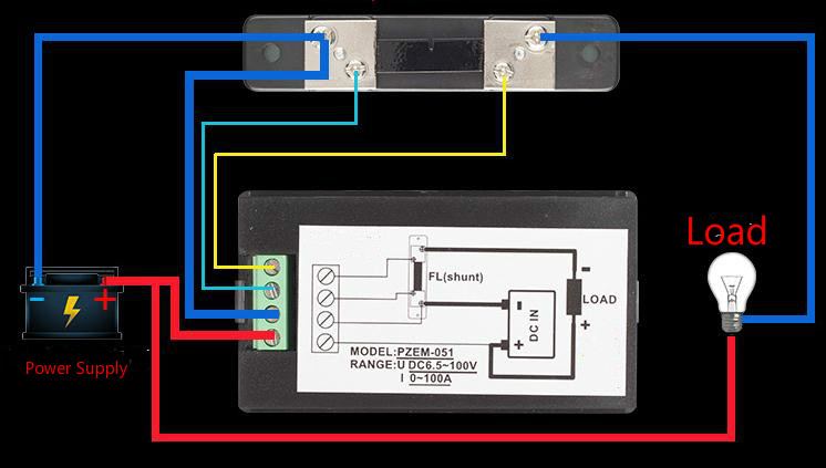
No matter the power come in or come out. Wiring is the same. The device that you want to monitor is that laod.
200141 meter only measure one direction current. please kindly refer to above wiring diagram.
There is no way to show incoming voltages only. Please find more details about button from this manual https://www.droking.com/cs/wp-content/uploads/2019/02/200141.pdf
Best regards
Donald J Steele
February 21, 2019 at 5:25 amPost count: 0Ok if I want to wire my wind turbine charge controller from controller to battery all DC not 3 phase Ac side. How would I wire that? Not the same way right? Would I need to put the battery negative on the top of shunt and charger on bottom instead of battery negative on bottomed bolt of shunt?
Donald J Steele
February 21, 2019 at 5:31 amPost count: 0Hello Donald J Steele,
We are sorry it is hard to confirm the bottom and top of shunt you mention.
If you want to measure the power from controller to battery, please hook it up as below. Battery is that load. The order of connection can’t be changed.
So far we only have AC meter for 2 phase circuit.
Best regards.
Donald J Steele
February 22, 2019 at 1:41 amPost count: 0Hello Donald J Steele,
About your questions”I want to see how much dc power is coming from a charge controller”
Our resposne is the same. Base on the above wiring diagram, it is available to check the power come out from charge controller. We wonder if you think the power drawed by battery is different from that come out from charge controller.
Best regards.
 George
April 18, 2019 at 5:15 amPost count: 0
George
April 18, 2019 at 5:15 amPost count: 0Hello George,
Thanks for writing in.
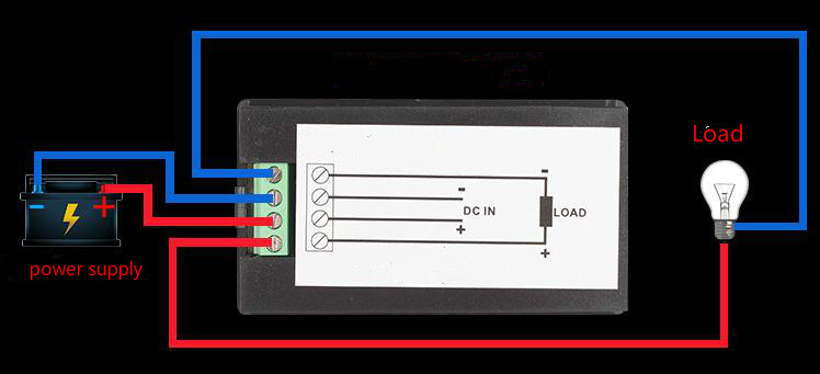
As per your description, we think it should be this item,200139
Wiring is as shown belown,
————————————————————————————————————————
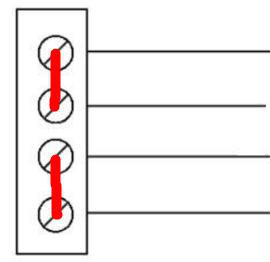
This image is to show you that actually there is short connection between 1,2 port and 3, 4 port. So you just need to connect power supply directly to 2, 3 port.
Best regards.
 Thomas Poulin
June 1, 2019 at 9:55 pmPost count: 0
Thomas Poulin
June 1, 2019 at 9:55 pmPost count: 0Hello
I have connected the 200141 meter to measure current and voltage from a 30-volt battery to a brushless DC motor controller on a bicycle. It works properly on level ground but on an uphill grade, drawing more current from the motor, the stops working and the screen is blank. This has happened to two of the meters, and I suspect that voltage spikes from the hub motor are causing something inside to fail.
Checking a failed one, Both the 2N60C and the 7133-1 regulator are all right but the rest of the circuit draws too much current and the output voltage from the 7133-1 is only about 1.15 volts. There are two integrated circuits inside, one connected to the display and one connected to the input voltage from the shunt. I think the one connected to the shunt is the failed part; if I cut the trace from the 7133-1, VCC goes up to 3.24 volts as it should.
Is it likely that a varistor (5KP200XA) across the meter input voltage will keep the meter from failing? I’d rather not ruin any more of them. Thank you for your help.
Regards
Tom Poulin
Riverside, CA, USA
-
AuthorPosts