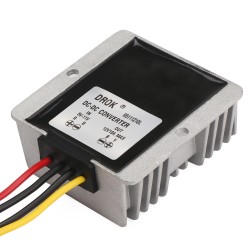
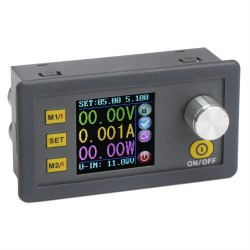
-10% Adjustable CC CV Buck Converter, Power Supply Module CC CV Buck Converter DC 5.3V~32V 24v Step Down Voltage Regulator 12A 160W Adapter/Driver

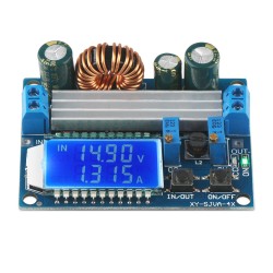
Adjustable CC CV Buck Converter, Power Supply Module CC CV Buck Converter DC 5.3V~32V 24v Step Down Voltage Regulator 12A 160W Adapter/Driver

  • Brand: Drok
  • Product Code: 2001711007
  • Availability: In Stock
  • $12.99
  • $11.69
  • Bulk Buy Discounts. Buy more please contact us
    Qty25102030+
    Price$11.10$10.52$9.94$9.59$9.35
-+

Ask Question

boomhauer asked [at] 2023-07-18 07:12:50

what are the specs of the diode that came with this unit?

No answer found for this question!

Q. Diode purpose Answer(s) 1

Ben asked [at] 2020-05-11 21:43:22

Diode purpose

Mine came with a large diode. What is it for? Where should it be connected? It's not shown in the manual.

DROK answered [at] 2020-05-13 09:11:26

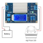
Dear customer, Diode is used to stop backflow from current when charging battery. Please connect it to output port. Best regards, DROK

John asked [at] 2020-04-21 23:22:23

My unit arrived from Amazon without assembly instructions, can you provide

DROK answered [at] 2020-04-22 04:03:29

Dear customer, We are sorry we don't have assembly instruction. Do you mean operation manual? We have pdf file on Amazon details page, here is the link, https://images-na.ssl-images-amazon.com/images/I/C1RCvx6bFMS.pdf Any more questions, please kindly contact us. Best regards, DROK

John Felice asked [at] 2019-12-04 19:24:30

How do I use the 5SQ045 shortly barrier rectrifier?

In my kit for the SKU 2001711007 I have a part 5SQ045 Shottky Barrier rectifier (from an internet search) that I need to know what or how to use it. Could you please provide instructions?

Drok answered [at] 2019-12-05 07:08:58

Dear customer, We don't sell 5SQ045 Shottky Barrier rectifier, is it from other seller? Best regards.

Charles Horton asked [at] 2019-08-23 03:54:34

need more infromation like a manual, block disgram, parts location

Manuals Block diagram Location of an On board 5v source for a micro cooling fan using the 5v being use for the display and boards IC

DROK answered [at] 2019-08-25 08:55:17

Dear customer, Thanks for writing in. This item doesn’t have on board 5v source. As factory doesn’t offer circuit diagram, we are sorry we can’t show you that. Beg your forgiveness. Best regards.

Showing 1 to 5 of 5 (1 Pages)

Parameters:

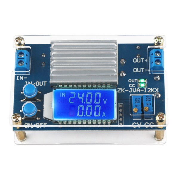
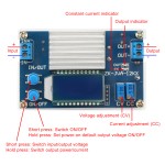
  • (1) Input voltage range: DC 5.3-32V (limit 35V; the lowest input 4V can achieve buck, but less than 5.3V input voltage, current measurement is inaccurate)
  • (2) Output voltage range: DC 1.2-32V (must ensure that the input voltage is higher than the output voltage, the minimum voltage difference is 0.8V)
  • (3) Output current: 8A for long-term stable work, strengthen the heat dissipation can reach 12A
  • (4) Output power: natural cooling 120W (within 8A), enhance cooling can reach 160W
  • (5) Voltage display: resolution 0.05V, range 0-32V
  • (6) Current display: resolution 0.01A, range 0-12A
  • (7) Conversion efficiency: about 96%
  • (8) Working current: 25mA or so
  • (9) Soft start: Yes (high power with load module may fail to start)
  • (10) Input reverse connection protection: yes
  • (11) Output stop current from feeding back: none (if you charge the battery, first power the module then connect to the battery, and ensure that the battery voltage is lower than the output voltage)
  • (12) Short circuit protection: yes
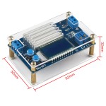
  • (13) Dimension: 82x 52x 32mm


Attentions:


  • 1. Module input IN- cannot short circuit with output OUT-, otherwise constant current function will be invalid.
  • 2. Please make sure that the power of the power supply is greater than the power required by the output load. Please reduce the power when the module is extremely hot.


Package Including:


  • 1 x Step_down Adapter


Attributes
input voltage5.3~32V
output current8A
output power120W
output voltage1.2~32V
output ways1
Will this regulate a variable input to a fixed output?
5.0
Happy Square Trade Customer 07/12/2020


I read, and reread the instructions to decide which mode of operation I wanted. I set both potentiometers to the full counter clockwise position. (The potentiometers are 20 turn devices.) Then I fed it the maximum voltage to which the unit is exposed, at 16v, and set the voltage 'in' pot to match that voltage, on the display. Then, I set the current limit pot until the unit supplied full speed (Required current)to the fan needed in my application. Then, I set the input voltage to the 12.0 volt minimum voltage the fan will see. The result is exactly what I want. I cycled the voltage input, several times. I powered the unit 24hrs, and tested hi & lo input voltages. It works perfectly. The output voltage and current remained constant. Note: If a person was careless with setup, he/she could burn the unit, in my opinion.

Perfect
5.0
Amazon Customer 02/12/2020

Forgive me for a too detailed explanation. I am a retired electronics technician by trade.

Functioned properly
5.0
Amazon Customer 26/11/2020


Perfect

A Decent Supply, No Mechanical Specifications
4.0
Ethan Lew 21/11/2020


Product functioned as described. No hardware to mount the unit in my project.

Simple and works fine
5.0
J. Krutsch 18/11/2020


The supply seems to work well for its intended use. No mechanical drawings/CAD models available to incorporate into a prototype design, though.

Write a review

Please login or register to review