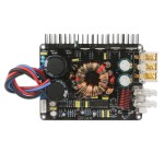
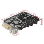
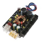
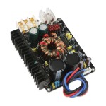
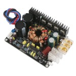
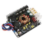
Click Image for Gallery
Ask Question
Parameters:
- Input voltage range: DC 9~16V
- Input power: 600W
- Conversion efficiency: can up to 90%
- Input current: 600W/13.8V=43.5A
- Output voltage: main: adjustable ±(22V~35V); auxiliary: ±15V, unstable
- Output power: total power 520W
- Output current: main: 8A*2; auxiliary: max 1.5A (can be used to power for the tone preamp panel)
- Power supply type: push-pull type
- Testing condition: input voltage DC 13.8V
- Typical application: DIY for tubes and power amplifiers such as LM1875, LM3886, TDA7293, 2SC5200/2SA1943
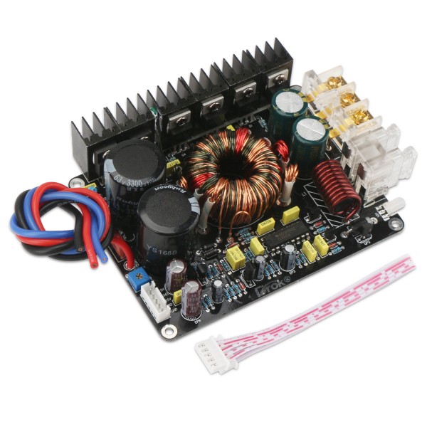
Terminals Introduction:
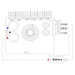
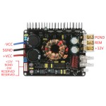
- +12V: connect to battery positive side or switching power supply +V
- REM: start voltage, connect to the +12V through the switch, or the CD host REMOUT line or ACC ignition key
- PGND: connect to battery negative side or put up iron, or switching power supply -V
- +VCC (red): main output voltage +, connect to amplifier voltage +
- SGND (black): amplifier "ground" , connect to amplifier "ground"
- -VCC (blue): main output voltage -, connect to amplifier voltage -
- +15V: preamp voltage +
- -15V: preamp voltage -
- Note: The outputs are ground DC after rectifier filter.
Safe Protection:
- 1. The reverse diode connected series in circuit has the input reverse polarity protection function; the fuse has the output voltage short circuit and overcurrent protection function.
- 2. With temperature detection circuit, lock the thermistor in circuit on the radiator, it can detect when the temperature is higher than 70 degrees Celsius, the power supply stopped working, then enters temperature protection state, when the temperature is reduced, it will automatically resume work.
- 3. With external voltage detection and protection circuit, and lead by PRO point (low level trigger protection). When the external circuit, such as the amplifier output short circuit, or other abnormalities, once detects the abnormal voltage, the power stops working immediately, and enters protective state to protect the switch tube from burnout.
Setting:
- 1. Testing power: please correctly connect the module input+ wire to battery+, and adjust the input voltage to 13.8V, then connect REM (can be connected to switch to 13.8V ) to battery +, battery - connect to PGND terminal, the power indicator light is on at this time, which means the power is normal working, and then you can test the voltage value of main voltage and auxiliary voltage.
- 2. (a). Testing temperature protection function: use tweezers to short the thermistor, at this time the red light is on, the green light is off, the module has no voltage output, release the tweezers, the red light is off, the green light is on, the power supply is restored to normal work, and the temperature protection is normal.
- (b). Testing external protection: lead the module ground with wire and touch PRO (low voltage start protection) protection sampling point, at this time the red light is on, no voltage output, rebooting the module REM wire can be restored to work, the voltage protection is normal.
- 3. If power supply test is normal, disconnect the input power wires, connect the amplifier or other load circuit, please note that the positive and negative side should be correctly connected, then connect the input power wires, make sure all is properly connected, then connect the control line, the equipment can work normally.
Package Including:
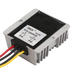
- 1 x Boost Volt Converter
| Attributes | |
| input voltage | 9~16V |
| output voltage | 22~35V |

