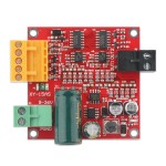
Click Image for Gallery
Ask Question
Parameters:
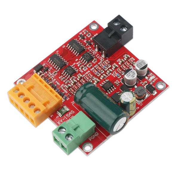
- 1. Power supply voltage: 6V~36V (voltage is too low, large load current easily lead to damage to the module, so the circuit board labeled 9-36V.)The power must not be reversed or more than 37V, or may burn the module, it is recommended that the power Input in series 20A fuse.
- 2. Drives without heat sink rated current 12A, rated current 12A ~ 15A need to do simple cooling, 15A ~ 20A need to do thick heat sink. (simple cooling - such as in the module below a 1mm thick thermal insulation silicone pad, and then 5mm copper column to the module fixed to the wall)
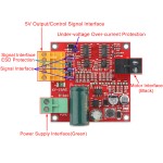
- 3. Control signal interface (orange) can provide users with external 5V, microcontroller no additional power supply, the maximum supply current is 0.5A.
- 4. Control signal high voltage: 2.0V ~ 5.5V, compatible with 3.3V and 5V TTL level;
- Control signal low voltage: 0V ~ 0.8V, 0V when floating;
- Control signal voltage is 5V, the control signal current is 50uA.
- 5. PWM effective range: 0.1% ~ 100.0%;
- PWM signal frequency range: 0 ~ 100KHz (recommend 20KHz);
- PWM minimum effective pulse width: 200ns.
- 6. Operating temperature -25°c ~ 80 °c
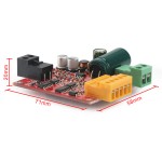
- 7. Mounting hole diameter: 3mm
Features:
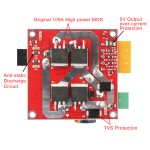
- 1. Industrial design, stable and reliable, with anti-static circuit, transient suppression protection, undervoltage protection, interface ESD and over-voltage protection.
- 2. Support 9~36V wide voltage range, the maximum sustained load current 12A (without heat sink), 15A (simple heat), 20A (thick large radiator).
- 3. Similar to L298 drive logic, three lines (PWM, IN1, IN2) control speed, revolution and connter revolution and brake.
- 4. Support full PWM, can be directly used to control the prevolution and connter revolution, PWM effective range is 0.1% ~ 100.0%.
- 5. Can provide 5V power supply for the microcontroller and other controllers, and it has 5V output overcurrent protection, and connect signal overvoltage protection.
How to use it:
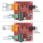
- The wiring method of using the microcontroller to control the motor rotation
- Single-chip power ground connect the drive module COM; PWM pin to the microcontroller's PWM output for speed, or directly connected to the high-level full speed operation; IN1, IN2 connect the two IO of microcontroller to control the motor revolution and connter revolution and Brakes; 5VO can provide 5V power supply for the microcontroller.
- The wiring method of only use the keys to control the motor revolution and connter revolution
- PB1 and PB2 are two keys. When the PB1 is pressed down and PB2 is not pressed, IN1 is high level, IN2 is low level, the motor is turning; when PB2 is pressed and PB1 is not pressed, IN1 is low level, IN2 is high level, Motor reverse; when PB1 and PB2 are bounced, IN1 and IN2 are low level, the motor brake.
Package Includes:
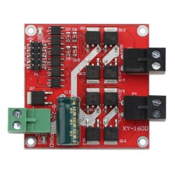
- 1 x DC Motor Drive Board ( DC Motor Speed Controller )
| Attributes | |
| input voltage | 6V~36V |
| output current | 12A~20A |
| output ways | 1 |

