


 to 6V 3A Buck Power Supply Module/Voltage Regulator/Power Adapter/Driver Module")


-47%


Click Image for Gallery


Ask Question
Product Features:
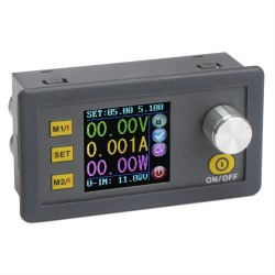
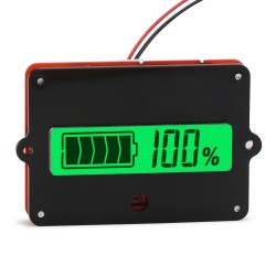
- 1. LCD can display input and output voltage, output current and output power.
- 2. Reverse connection protection at input terminal, reverse connection will not burn.
- 3. Can be boost, can be buck, the output voltage range is DC 0.5-30V, can be arbitrary regulated, the current limit range 0-4A, can be arbitrary regulated.
- 4. Stop current flowing backwards protection at output terminal.
- 5. Button control output ON / OFF status, and you can set the power-on default is ON or OFF.
- 6. Using descending chip as the main controller, external 60V 75A MOS tube as a switch, double 60V 5A SS56 Schottky as rectification, 60V permissible voltage value.
- 7. Small output ripple, with LC filter.
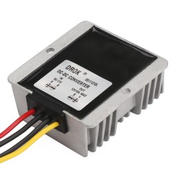
- 8. With heat sink, module support isolation column.
Parameters:
- Input voltage range: DC 5.5~30V (when the input voltage is 5V, the boost and buck can be achieved, but the voltage and current measurement is inaccurate; under 4.7V, under voltage protection will be activated)
- Output voltage range: DC 0.5-30V
- Output current: can stably work at 3A for a long time, when enhance heat dissipation can reach 4A
- Output power: 35W (natural cooling), when enhance heat dissipation can reach 50W
- Voltage display resolution: 0.05V
- Current display resolution: 0.005A
- Conversion rate: about 88%
- Soft start: Yes, (a large power load module may fail when it is started)
- Input reverse connection protection: yes
- Output stop the current from feeding back protection: yes
- Short circuit protection: yes
- Working frequency: 180KHZ
- Size: 66 * 48 * 21mm
- Mounting hole: 4mm in diameter
Function Description:
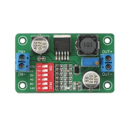
- 1. There are IN/OUT, ON/OFF two buttons on the module, IN/OUT button to switch the input voltage and output voltage display, hold press to switch the output current and output power display; ON/OFF button control output ON or OFF, hold press can set the default output state is ON or OFF of the next time power-on.
- 2. CC is the current setting potentiometer, clockwise rotation can increase the set current, when the load current reaches the set current, enter the constant current state, CC constant current indicator (red) light will be on; CV is the voltage setting potentiometer, clockwise rotation can increase the output voltage. ON indicator is the output status indicator, it is on when output voltage, otherwise it is off.
Application:
- 1. Used as an ordinary buck-boost module with over-current protection
- (1) Adjust the CV constant voltage potentiometer to adjust output voltage to reach the voltage you want.
- (2) Measure the output short-circuit current with 10A multimeter (connect the two test leads directly to the output end), and adjust the CC constant current potentiometer to make the output current reach the preset over-current protection value. (For example, if the current value displayed by the multimeter is 2A, the maximum current will only reach 2A when you use the module. When the current reaches 2A, the red CC CV indicator is on, otherwise the indicator is off)
- Note: when using in this state, connect to the load, there will be a voltage drop of 0 ~ 0.2V due to the current sampling resistor at the output. At the same time, the input and output leads will have a certain linear voltage drop, this is a normal phenomenon.
- 2. Used as a battery charger
- Without constant current function of the module cannot be used to charge the battery, due to the power of the battery and the charger pressure drop is large, resulting in charging current is too large, which will cause damage to the battery, therefore, should use constant current charging the battery at the beginning, when charge to a certain extent automatically switch back to constant voltage charging.
- (1) Confirm the float voltage and charging current for the rechargeable battery you need (if the lithium battery parameter is 3.7V/2200mAh, then the float voltage is 4.2V and the maximum charging current is 1C, ie 2200mA).
- (2) Under no-load condition, use multimeter to measure the output voltage and adjust the CV potentiometer to make the output voltage reaches the float voltage. (If charge the 3.7V lithium battery, adjust the output voltage to 4.2V).
- (3) Measure the output short-circuit current with 10A multimeter (directly connect the two test leads to the output terminal), and adjust the CC potentiometer so that the output current reaches the predetermined charge current value.
- (4) Connect the battery, charging.
- (Steps 1, 2 and 3 are as follows: input terminal connect to power supply, the output is not connected to the battery load)
- 3. As a high-power LED constant current driver module
- (1) Make sure the operating current and the maximum operating voltage of the LED you need to drive;
- (2) Under no-load condition, use the multimeter to measure the output voltage, and adjust the CV potentiometer to make the output voltage reach the maximum operating voltage of the LED.
- (3) Use a 10A multimeter to measure the output short-circuit current, and adjust the CC potentiometer at the same time, to make the output current reach the preset LED operating current;
- (4) Connect to the LED, test module.
- (Steps 1, 2, and 3 are as follows: Input terminal connect to the power and the output is with no-load.)
- Note: when the module is used over 3A 35W, please strengthen the heat dissipation.
Attentions:
- 1. Module input IN- cannot short circuit with output OUT-, otherwise constant current function will be invalid.
- 2. Please make sure that the power of the power supply is greater than the power required by the output load.
- 3. If the module is output with full load, the input voltage should be over 8V. When the input voltage is 5V, the output power is about 15W, and the voltage current meter is invalid. Max module current value is 4A, which is limited to the maximum output power, for example, if the output voltage is 17V, the output current should not exceed 2A.
- 4. Module is designed with output short-circuit protection, if activates short-circuit protection, the module will automatically shut down the output, the module can be restored if power on again, if your power supply without output current limiting protection, it is recommended that the module input front-end fuse in series to increase the safety factor.
- 5. The module has input under-voltage protection function, the default is about 4.7V. Below this value, the output will be disconnected automatically and the module can be restored if power on again (note it is the voltage at the module port. When the input current is relatively large, please do not ignore the partial pressure on the input wire).
Package Including:
1 x Boost Buck Module ( Charger/Adapter/Regulator/Driver )
| Attributes | |
| input voltage | 5.5~30V |
| output ways | 1 |
Auto Boost Buck Converter, 35W Power Supply Module/Adapter DC 5.5~30V to 0.5~30V 3A Boost Buck Converter/Adjustable Regulator DC 5V 12V 24V Charger/Driver
- Brand: Drok
- Product Code: 2001711006
- Availability: In Stock
- $15.50
- $8.25
-
Bulk Buy Discounts. Buy more please contact us
Qty 2 5 10 30+ Price $7.75 $7.45 $7.25 $6.95
 |  |  |  |
Related Products
 -35%
-35%DC voltage step up regulator DC 6-30V 5V to DC 7-32V 12V 24V 5A Adjustable voltage boost converter, LCD Power Supply Module Voltage Current Amp Display Transformer
About this item Clear LCD Display --- The boost board ..
$14.99 $9.79
 -13%
-13%Adjustable Voltage Regulator DC Buck Boost Converter 6.0V-36V 9v 12v to DC 0.6-36V 24v 5A Power Supply Panel, Constant Current Volt Step Up Down Module
FeatureEasy to Use --- allows to set volts and limit the current, power on off and accurate voltage ..
$23.99 $20.87
-35%
About this item
Clear LCD Display --- The boost ..
$14.99 $9.79
-13%FeatureEasy to Use --- allows to set volts and limit the current, power on off and accurate voltage ..
$23.99 $20.87